The Critical Role of Solenoid Valves in Refrigeration Systems: A Comprehensive Guide
16/10/2026 · 121 مشاهدة
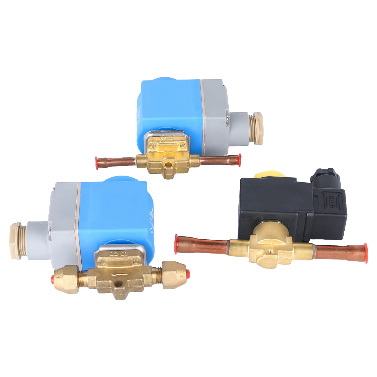
In the complex world of refrigeration and HVAC systems, every component plays a vital role in ensuring optimal performance, energy efficiency, and system longevity. Among these essential components, the solenoid valve stands out as one of the most critical control devices that often goes unnoticed until it fails. Understanding the function and importance of solenoid valves in refrigeration systems is essential for engineers, technicians, and facility managers alike. This article explores the multifaceted role of solenoid valves in refrigeration units, their applications, and why proper selection and maintenance are crucial for your system‘s success.
In the complex world of refrigeration and HVAC systems, every component plays a vital role in ensuring optimal performance, energy efficiency, and system longevity. Among these essential components, the solenoid valve stands out as one of the most critical control devices that often goes unnoticed until it fails. Understanding the function and importance of solenoid valves in refrigeration systems is essential for engineers, technicians, and facility managers alike.
This article explores the multifaceted role of solenoid valves in refrigeration units, their applications, and why proper selection and maintenance are crucial for your system's success.
What a solenoid valve actually does
Strip away the catalogue language and a solenoid valve performs one function: it opens or closes a refrigerant line on an electrical signal. There is no modulation, no proportional control and no feedback. A coil produces a magnetic field, the field lifts a plunger off a seat, and refrigerant flows. When the signal disappears, a return spring pushes the plunger back down and the valve closes.
That simplicity is exactly why the device is trusted with jobs that matter. A pump-down cycle depends on the liquid line valve closing completely every time, thousands of times a year. A hot gas defrost depends on a valve opening against a pressure difference in the middle of a winter night. Neither job tolerates a valve that closes most of the way.
The parts that do the work are few: the coil, the fixed core inside it, the plunger, the return spring, the seat and — on larger sizes — a diaphragm or piston that lets the small magnetic force control a much larger port. Every failure mode in the field traces back to one of those parts, or to what the system pushed through them.
Where solenoid valves sit in a refrigeration circuit
A solenoid valve is only as good as the position it occupies, and the positions are standard enough to list:
Liquid line, ahead of the expansion valve. This is the pump-down valve. When the thermostat is satisfied, the compressor stops and this valve closes, so the compressor can pull the low side down to the pump-down setpoint and stop with refrigerant stored on the high side instead of migrating into the crankcase. If the valve leaks, the compressor restarts on pressure rise all night and the fault looks like a control problem rather than a valve problem.
Hot gas branch for defrost. The valve opens to route discharge gas through the evaporator, melting the frost from the inside. It works at the highest differential in the plant, which is why MOPD matters here more than anywhere else.
Suction line for capacity control. On multi-evaporator systems, closing one valve takes one evaporator out of service without stopping the compressor. The same arrangement is used for unloaded starts.
Condenser water. On water-cooled condensing units, a solenoid valve on the cooling water line stops flow when the compressor stops, so the water is not wasted overnight.
Liquid injection and oil management. Economised systems and low-temperature racks use small solenoid valves to admit liquid for injection or to control oil return, and these are usually the smallest and most overlooked valves on the job.
Normally closed is the default, and that is a safety decision
Most refrigeration solenoid valves are normally closed: no power, no flow. This is not an arbitrary convention. The failure that matters in a refrigeration plant is the compressor running without control, and a normally closed valve fails in the safe direction for pump-down, for hot gas, and for liquid injection.
Normally open valves exist for the opposite requirement — circuits that must stay open when the control circuit is de-energised, such as certain oil cooling loops and some water circuits where stopping flow would cause more damage than continuing it. The choice should be made from the failure analysis, not from what is on the shelf.
When replacing a valve, check the function before the size. An NC valve installed where the circuit expects NO behaves perfectly during normal running and fails in exactly the wrong way during a shutdown.
Sizing: Kv, MOPD and why the port is smaller than the line
Two numbers decide whether a valve works in a given circuit, and neither is the pipe diameter.
Kv describes flow capacity: the volume of water in cubic metres per hour that passes at a pressure drop of one bar. Convert for the refrigerant in use, then check the resulting pressure drop against what the system can afford. A valve that is too small shows up as a permanent pressure drop across the liquid line, flash gas at the expansion valve and a capacity shortfall that nobody can trace.
MOPD — maximum opening pressure differential — is the pressure difference the coil can pull the plunger against. It is not the same as the working pressure of the body. An AC coil on a small orifice may open against 10 bar; the same body with a larger orifice may only manage 4 bar, and a hot gas defrost line can easily exceed that at low ambient. This is the single most common specification error we see: a valve chosen by connection size that cannot physically open under the conditions it is installed in.
The port being smaller than the line is normal and not a mistake. The valve body is sized to the line so it can be brazed in place; the orifice is sized to the flow.
Materials: the refrigerant and the oil decide for you
Brass bodies with copper connections cover the great majority of HFC work. Stainless steel enters the picture with ammonia and with CO2, where brass is either chemically unsuitable or not permitted by the code the plant is built to.
Seals are where the details live. NBR is the general-purpose choice for HFC and mineral or POE oil. HNBR handles higher temperatures and holds up better in POE systems where the oil is more aggressive. PTFE is used where temperatures climb above what elastomers tolerate, and in positions where the valve sits hot for long periods.
A2L refrigerants such as R32 and R454B have not changed the principle, but they have raised the price of a leak. Charge sizes are smaller and the margin for seat leakage is thinner, so the strainer, the filter drier and the brazing discipline matter more than they did on R22.
Installation mistakes that kill valves in the first season
Brazing without protecting the valve. The seat and the plunger are a few centimetres from the joint. Wet rag, heat sink paste or a wet wrap around the body, and the valve body kept below the temperature where the seals degrade. A valve that passes factory testing and leaks in service was usually cooked during installation.
Debris in the line. Copper chips from cutting, flux residue, swarf from a threaded joint — all of it ends up on the seat. Every new installation should be flushed, and a filter drier should be in the circuit before the valve sees refrigerant. Debris damage is the most common reason a valve that worked for three months stops closing fully.
Wrong direction. The arrow on the body is the flow direction and it is not decorative. A valve installed backwards may appear to work on a small pressure difference and fail as soon as the differential rises.
Manual stem left partly open. Lifting stems exist for commissioning and for emergency operation. If one is left raised after start-up, the valve is bypassed and the pump-down cycle quietly stops working. It is worth physically checking every stem on a new plant.
Over-torqued flare connections and distorted bodies. Brass deforms. A flare nut tightened until it stops moving has usually been tightened past the point where the cone seals properly.
Electrical details that get skipped
Coil voltage tolerance is typically plus or minus ten percent, and on a long control run the drop at the far end of a 24 V circuit can exceed that. The symptom is a valve that buzzes instead of opening, and a coil that runs hot and eventually fails while the voltage at the panel looks perfect.
AC coils draw an inrush current several times the holding current. That matters for the control transformer and for the contacts in the circuit, and it is the reason a small relay that worked with one valve fails when a second valve is added to the same circuit.
DC coils — including rectified AC coils with a bridge inside the coil can — do not have the same inrush behaviour, but they are polarity sensitive. Reversed wiring gives no movement at all, and the installer concludes the valve is faulty.
Coil temperature is a design parameter. A coil rated for a 50 °C ambient in a plant room that reaches 60 °C in August will fail early, and the failure will be blamed on the valve.
Troubleshooting: five symptoms and what they usually mean
No flow, no click, coil cold. Open circuit in the coil or no signal. Measure the coil resistance and the voltage at the coil terminals, not at the panel.
Buzzing. AC coil with insufficient voltage, or a plunger that cannot travel fully because the differential exceeds MOPD. The buzzing is the plunger oscillating; it destroys the coil if it continues.
Valve will not close. Dirt on the seat, a worn seat after years of service, or a manual stem left open. Disassemble and inspect the seat before replacing the whole valve.
Frost or condensation at the outlet. The valve is passing when it should be closed. Confirm the coil is de-energised, then check the seat.
Repeated coil failures. Look at supply voltage, at short cycling from a control loop that is hunting, and at moisture ingress through the coil lead entry.
When a solenoid valve is the wrong tool
A solenoid valve is on or off. If the job needs partial flow — holding a room within half a degree, matching capacity to a changing load, or keeping suction pressure stable during a pulldown — an on/off valve will produce a cycle that swings around the setpoint and wears the compressor. Electronic expansion valves and stepper-driven valves exist for that job, and using a solenoid plus a thermostat where a modulating valve belongs is a design decision that shows up later as short compressor life.
The same applies to very large lines. Above a certain port size the coil needed to lift the plunger becomes impractical, and pilot-operated or motorised valves take over. Sizing a solenoid valve into a 4-inch liquid line because the schedule lists one is how plants end up with a valve that opens only when the differential is low.
Spares policy for a plant room
Solenoid valves fail at the worst possible moment, and the difference between a two-hour repair and a two-day shutdown is usually what is on the shelf. A practical minimum: one spare coil per voltage and size in use, one complete valve per critical circuit, and an O-ring and diaphragm kit for the sizes that appear more than twice in the plant. Write the coil voltage and the valve model on the plant room wall, because the label on a coil that has been in service for eight years is rarely readable.
A selection checklist
Before ordering, answer these in writing: what the valve must do when de-energised (NC or NO); the line size and the required Kv at the actual refrigerant; the MOPD against the highest differential the circuit will see, including defrost and low ambient conditions; the refrigerant and oil, which determine the seal material; coil voltage, frequency and AC or DC; the connection type; the ambient temperature at the valve, not at the plant room door; and whether a manual lifting stem or a sight glass is needed for commissioning.
Get those seven answers right and the valve becomes a component that runs for a decade without attention. Get them wrong and it becomes the part that nobody can explain, in a system that never quite performs.